Well, sorry folks, I never really got started up again once I got back from holiday - too many things in real life (TM) got in the way.
A partial success - I did get it working, and a real new game created (albeit a simple one), but not much else.
Roll on Winter 2013 - I'm not going anywhere and I'm going all out to win next time :)
Wednesday, 31 July 2013
Tuesday, 23 July 2013
I'm back .....

Two problems...... firstly the sound doesn't work, and I've also realised that the Serial Register shifts left not right ..... so some bug fixes needed here :)
L8R: Fixed the emulation bug and modified the utility functions to work differently, but the sound still doesn't work on Java.
Saturday, 6 July 2013
Leave of absence
I may will do a few bits of design though.
Sad I know.
TTFN.
Friday, 5 July 2013
Demo Game
Not only can you watch the game on your TV and play the board game you can now play it on your home computer.
It is a slightly cut down version, because it is difficult to fit all 37 books of rules into a microcontroller with 512 bytes of ROM memory (I did consider interfacing an SD RAM Card but it was too challenging).

Playing the game is simple. Download the emulator and the "Numberwang" game pack, and unzip both files. Put all the files in the same directory.
Run it with:
java -jar funem.jar numberwang.bin
then select Debug/Run on the menus and click on the Game window. To play the game, choose your number (from 1-8) by pressing the button (keys A-H on the keyboard) and it will tell you whether or not it is Numberwang by lighting the green or red LED at the bottom of the screen. You can also "rotate the board" for added realism (R key), and play it as a 2 or more player game by passing the game around between 2 or more players.
The game zip contains the source and the background SVG, the only files that are actually needed are numberwang.bin (program code and hardware description) and numberwang.png (the backdrop picture).
This is just a test game to check everything that works and that the "BIOS" file is useable. Creating this game took about 20 minutes, but 2-3 times as long was spent tweaking and bug fixing the BIOS. I still haven't cracked the sound yet, it warbles a fair bit :)
I am going away soon ; when I get back I will have a go at writing a "proper" game, probably one of the three original games, then have a go at writing a real original game.
Thursday, 4 July 2013
Updated BIOS/System common code
It's probably mostly complete, though I might add other specific routines like "Increment RAM(B) and set carry if zero" (which is there already).
Anyway, next up, writing a demo game.
BIOS early release
It does, however, do quite a lot of the work.
The main part is the light generation. The idea is that the main loop does something like:
do {
light(led1)
light(led2)
if (something) light(led3)
} while (!timeOut)
i.e. lighting each light in turn. Decoding and lighting the leds takes roughly the same amount of processor time each time. So we can create a timing system that has a counter which counts up to 15x16 (technical reasons) "led lighting instances" and this will take a predictable amount of time.
We can also use this to track audio. By having an audio counter and adding a pitch value on it, we can turn the sound off and on again on overflow, giving 15 different reasonably predictable pitches. You couldn't play a tune on it much,but it's okay for simple sound FX.
When the timeout occurs the coder can scan the buttons (functions available for this) and update the status of the game accordingly.
I am a bit undecided about this. Writing code from scratch for each game allows more efficiency - one can use SKGBZ and so on, rather than doing it the way I've done it. But it does, after a fashion promote some hardware independence, so you have code like
redled = @redLED(L2:D3,120,200)
..
clra
aisc redled
jsrp LightLED
The first isn't 'real' assembler, it is a directive to put a red LED at 120,200 on the game space, and connected it to L2 and D3 (so it lights when L2 = 1 and D3 = 0). The code then uses that provied ID "redled" to light it without actually knowing how the led is connected. It works it out from the ID.
This is a good way to program, it's just when using 1/4 of the available ROM on these routines you start to worry about whether it will fit or not. Hopefully it will, because these routines do a lot of the heavy lifting. If not I can always use a COP420/421 as a sort of "COP410/1 with more ROM memory" - the connections and code are binary compatible.
The missing feature is a random number generator. I wrote one for the TMS1000 Simon game, which hopefully can be used. It wasn't brilliant, but it's good enough
Wednesday, 3 July 2013
A neat trick
Yesterday evening, pondering the software for this thing, I came up with something that might actually be original.
It's this:
aisc 14
aisc 14
aisc 15
aisc 5
aisc 8
aisc is add immediate and skip on carry, i.e. aisc 14 adds 14 to the (4 bit) accumulator and skips the next instruction if the result is more than 15 (the largest value in a 4 bit accumulator).
It looks like gibberish. You add 5 numbers in a row.
But it doesn't do that, because different values skip different instructions. So if you start with 1 you do the first 2 and skip the third (1->15->13) instructions, but if you start with 2 you do the first and third and skip the second (2->0->15)
What it actually does is to map 0,1,2,3 -> 1,2,4,8 - it converts a bit number to a bit mask. (the results are 0001 0010 0100 1000 in binary). This is going to be very useful in the system routines which access hardware by ID (e.g. LEDs are accessed using two 2-bit values in a nibble, the L line to set to '1' and the D line to set to '0').
I figured it out more or less by trial and error by hand having wondered if it were possible to do this sequence this way (an index lookup or loop would be bigger and slower). Having done that I then wrote a Java program to search for these sort of aisc sequences (combined with comp, the 1's complement instruction) for other useful mappings (e.g. 0,1,2,3 -> 14,13,11,7, the 1's complement of the above). But it didn't turn up anything much of any use.
It's one of the things I like about coding for a 4-bit processor. It makes you think. I learnt to code (on a real machine) on an SC/MP Introkit (basically the same as Sinclair's MK14) and it taught you about things like efficiency.
When I worked as a pro developer I quite often came up against outrageous wastes of either CPU time or Memory space by other coders that were quite unnecessary. On their own these don't cause a problem, but if you have lots of them in the same system then it drags the whole thing down.
The trick is to get the balance right - don't spend hours optimising every cycle out (unless it is something like an Atari 2600 - or this where space/time is important) versus a quick and lazy solution.
I think this basic fault is why Windows 3.11 (for example) worked on a 386-20 very nicely, but the prettier 32 bit versions are slower on a machine which is umpteen times faster and has thousands of times more memory and much of the drawing work done by a graphics card (I'm old enough to have developed using 32Mb Hard Disk partitions on Windows 3.1). If you read the book "Showstopper" about the development of Windows NT David Cutler (the lead) has one of this as his main premises.
Tuesday, 2 July 2013
Sound and Background added.

The latter was nicked from the Watchman project - rather than generating a simple tone it's a modulated tone, which gives it that authentic "tuneless Sinclair Spectrum music" sound that goes with cheapo sound hardware.
Sort of working

The screen has 3 LEDs - a Red one, that is on, the Yellow one (top left) and a Green one (bottom centre) that are off. There are two switches - a push button (black square on the left) and a slide switch (on the right).
It is actually running real code - you can see a little bt of it in the window and it doesn't do anything other than switch the RED LED on and off as the slide switch goes from left to right.
There's no sound, yet, though the hooks for it are there.
I really just wrote it for testing so I could see if the whole 'wiring up' thing works. And it appears to work fine. Once the speaker is installed the basic emulator will be finished, and then there is just the matter of writing some code for it. I also want to spruce up the graphic display a bit.
Useless factoid of the day.
Thus in a co-processor system with the CDP1802 one could have the following assembler code.
OMG
SEX
.... okay, it's been a long day.
Documentation
Well, I thought I'd better write some documentation .....
Monday, 1 July 2013
Kevin Savetz's book

If you ever want an entertaining read and you are a 70s/80s computer geek, it's highly recommended.
Actually a lot of the book could be about me, (if you cross out where it says "Atari" and replace it with "Sharp MZ-80K and BBC Micro."), I never owned any Atari kit before an Atari ST.
First release of Assembler and Emulator
I've added to the links bar links to zips of the Assembler and Emulator for the Funtronics hardware.
These should be very much considered v0.1 (actually they are .....) but they do work, admittedly you can't do much with them, yet.
The souce is set up for Eclipse and both were developed under Java 7, though 6 will probably work. (not so sure about the audio)
The emulator has no actual hardware so whilst it will run COP411 binaries it won't interact with anything external.
Finding a graphic for Assembly Language isn't that easy and I came up with this stack. I can't really see a HLL for this machine being developed - but having said that, there's a machine called the "Gakken GMC-4" you can get which is a 4 bit Microcomputer based on a Tandy (Radio Shack) trainer from the 1980s. Someone wrote a GCC back end for it and someone else wrote a Basic compiler. So you never know. Given that it has about 80 bytes of program memory (4 bit memory at that) you couldn't do much with it (but then you couldn't with Atari 2600 BASIC either ....)
So, anyway, the next thing is to develop the hardware interface. This will probably be integrated into the assembler, because there is no consistent hardware for this machine, merely a bunch of LEDs, switches and buttons that appear in various places on the game box. So there will be some sort of descriptive language for that that is integrated into the assembler.
The hardware will be a sort of crossover between Jacks and Red Light Green Light. It will take the basic design of RLGL and add to it the option of the keyboard matrix in Jacks. While the patents are pretty similar, there are silly design differences - in RLGL the power switch is connected to G2 and the speaker to G3. In Jacks the power switch is connected to G3 and the speaker to G1. (Port G is a configurable I/O port).
I did have the idea of making the design completely configurable but I thought that was going a bit far. I will basically stick with the RLGL hardware (4,296,926) with the Switches 16a-f added as in Jacks (4,355,806). This will be extended slightly on both, so that there are a possible total of 8 switches mapped to L4/L5 and D0/D1/D2/D3 (giving a total of 8 switches, and G0 and G1) and 16 LEDs - with their anodes driven by L0/L1/L2/L3 sinking into D0/D1/D2/D3.
Working COP411 Emulator

One oddity is that whilst there are only 32 nibbles of RAM, the mapping actually allows for 64 bits of RAM (Bd is 4 bits, Br is 2 bits).
A consequence of this is that in the map every nibble appears twice - e.g. $00,$08 ... $01,$09 and so on. (The hardware ignores bit 3 of the Bd register).
Now I need to cannibalise the Assembler I wrote for the watch project so it will assemble COP411 assembler. There is actually a working COP411 assembler available, but I want to be able to extend it easily.
Sunday, 30 June 2013
About the Processor.
There seem to be two popular 4-bit old Microcontroller families - the Texas Instruments TMS1x00 series, most famously in Simon, Merlin and the Hornby Railway system, and National Semiconductors' COP4 series - which was in Atari hardware and the Mattel sports hardware. There are a few others - the Entex Select-A-Game uses a Hitachi HD38800 processor for example, but not many I have come across. It is also in my all time favourite handheld, the utterly pointless Invisible Alien Neutraliser (IAN) which would have been the Retrochallenge if I could have come up with any use for it. (the actual use doesn't count IMO !)
This is one of the babies of the COP4 family - it has 512 bytes of ROM and 32 nibbles (e.g. 4 bit values) of data memory - about half the power of a TMS1000. It is fairly slow - about 50-60khz as a base CPU clock, but that's quite adequate for this kind of thing.
The design is fairly similar to that of the TMS1000 at heart - there is an Accumulator, a pair of registers which address memory, a Carry / Status flag and assorted I/O ports.
The instruction set is not unusual - with one exception. The microcontroller has an instruction XAD 3,15 (which swaps A with memory bank 3, location 15 directly). This is a bit out on its own (the COP444 for example can do this with every memory location).
I think this is to deal with the major problem with the SM-510 in the Watchman - without it it would have exactly the same problem regarding indirect writes (it is very difficult to get an SM-510 to write a value stored in one location to an address stored in a second .... see the Watchman blog if you want the gory details). What this instruction does is to sort of co-opt RAM(3:15) as another internal register in the MCU (even though it isn't).
It is unusual for these processors to have logic operations - unusually the processor has an XOR instruction (which is odd really, because an XOR instruction is the same as ADD but you don't carry .....). I think this is a hangover from the origin of these devices (most of them are converted calculator chips)
What is a Funtronics Handheld ?
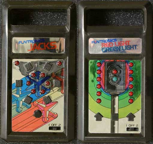
They are Mattel electronic toys from the early 1980s. There are five of them in total - these two, "Tag" and "Drag Race" (which is a competition version of the RedLight game produced for Hot Wheels) and "Tag Chat" which is a French version of Tag. The latter two just have different labels, so there are only three really.
They are all the same, with different layouts and (slightly) different circuitry in places. Primarily the buttons - the "Jacks" game has more buttons than the system has inputs (Red Light does not) so Jacks multiplexes its buttons.
The boxes contain a mixture of LEDs and Buttons in various arrangements. Inside there is a Piezo speaker and a COP410 4 Bit Microcontroller. This has 512 bytes of ROM and 32 bytes of RAM, and runs at 50,000 instructions per second. COP processors and their family members were one of the commonplace chips in these sort of toys along with Texas TMS1x00 series (Total Control 4), the Hitachi HD44 (Select-A-Game) series and the Rockwell series (Battlestar Galactica).
My challenge for this Summer is to reproduce at least one of them electronically, then to create a new one. This is possible because of the Patents Database, which contains all sorts of useful information about electronic gadgetry, and contains a full description of how "Jacks" and "Red Light" (specifically) actually work, complete with circuit diagrams. It doesn't contain the code though (a couple of patents do)
I like and always have liked working with limited hardware. I like the challenge of getting something worthwhile out of something which has limited power and parts. Programming 4 bit microcontrollers is also rather fun, albeit a bit mind numbing at times (though the COP instruction set is better than the TI one, even if it does have less RAM).
Finally, here's a video of an advertisement showing one in action, sandwiched between Mr Spock advertising a Telephone and Mr Reagan advertising himself.
https://www.youtube.com/watch?v=vb5NcTeGXKQ
Picture courtesy of http://www.handheldmuseum.com
The old Retrochallenge
This is actually my second, arguably third Retrochallenge Summer 2013 (the other one didn't really get started).
The first attempt was an similar kind of thing to his based around a watch. This was based around a processor called the Sharp SM-510.
I really gave it all I could. But I just couldn't code with the thing. Everything - virtually everything - required huge amounts of code simply to do the simplest task.
Not that I minded that, but it required increasingly obscure tricks just to get it to do something that was relatively simple - even on a TMS1x00 or a COP4xx it would be a lot easier.
So in the end, I decided to abandon it in favour of this challenge.
I'd like to apologise to Dale for putting up with me continually changing my mind. I really did want to do the Watch thing but it is driving me almost literally round the bend.
And so it begins.
You may have noticed that it hasn't started yet. I'm sort of cheating a bit here. The reason is that I'm taking my mob to Orlando this July.
I didn't think the suggestion that "we can't go because I'm doing the Retrochallenge in July" would go down very well.
So I am going to do a fair bit of the preparation in June and do the actual challenge bit in July.
L8R : Well, that was the plan anyway. Because I faffed around deciding what the challenge was going to be, I've wasted about a fortnight. I can cannibalise some bits of the old challenge especially the assembler .... but it's now a 2 week Retrochallenge plus a bit.
Subscribe to:
Posts (Atom)